Software
The first thing to do is create a development environment on your computer. The DirtyWatts microcontroller uses a tool called PlatformIO to handle uploading the C++ code to the NodeMCU.
To setup your windows/macos/linux device for development:
These are the steps. Setting up your computer to do the work is one of the hard stages, so good luck!
- Download and install Git if you don't have it already. You won't be using it directly, but
- Here is some info about Git
- You can install it for Windows, MacOS (via Xcode), MacOS (via Homebrew), Linux
- Download and install Visual Studio Code (VSCode) if you don't have it already.
- VSCode is a code editor, and you can get an introduction here
- Open VS Code and install the PlatformIO extension.
- You might be used to the Arduino IDE for programming your microcontrollers. PlatformIO is the professional version of it and automatically handles installing the dependencies for your particular controller using the previously installed copy of Git.
- Here is an installation guide
- You might be used to the Arduino IDE for programming your microcontrollers. PlatformIO is the professional version of it and automatically handles installing the dependencies for your particular controller using the previously installed copy of Git.
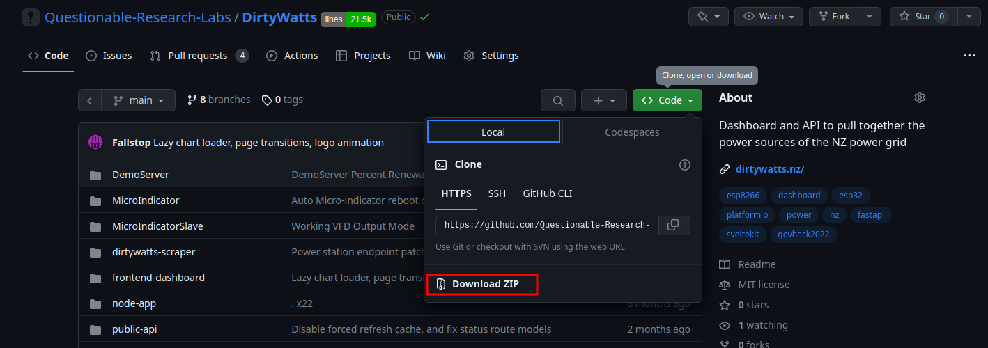
- Download and extract the DirtyWatts codebase from Questionable-Research-Labs/DirtyWatts.
-
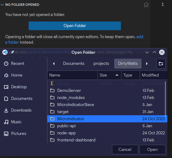
- Open the DirtyWatts/MicroIndicator folder:
Here is a guide
Make changes to fit your device
You are now ready to start making changes to your code!
Open this file src/config.h , there are some configuration options you might need to change:
#pragma once


#ifdef OUTPUT_NEOPIXEL
    // Pin that the Neo Pixels are connected to
    #define NeoPixelPin D1D4

    // D1Max onnumber esp8266of LEDs in chain
    #define NeoPixelCount 30

    // Pixel type flags, add together as needed
    //   NEO_KHZ800  800 KHz bitstream (most NeoPixel products w/WS2812 LEDs)
    //   NEO_KHZ400  400 KHz (classic 'v1' (not v2) FLORA pixels, WS2811 drivers)
    //   NEO_GRB     Pixels are wired for GRB bitstream (most NeoPixel products)
    //   NEO_RGB     Pixels are wired for RGB bitstream (v1 FLORA pixels, not v2)
    //   NEO_RGBW    Pixels are wired for RGBW bitstream (NeoPixel RGBW products)
    #define NeoPixelFlags NEO_GRB + NEO_KHZ800

#endif

#define APIRequestInterval 2000	 // 202 secondsseconds, measured in milliseconds

#define ApiErrorColour 150, 150, 255  // Light Blue

#ifdef OUTPUT_RELAY
    #define RelayPin 12
#endif
This code is for telling the microcontroller which pin you plugged the data wire into.
See the #define NeoPixelPin D1 This creating a variable (a name) called NeoPixelPin and giving it the value D1. If you plugged your data wire into a different pin, you can use say what it is here. You probably don't need to do that.
Next see the #define NeoPixelCount 30 This is making another variable (name) called NeoPixelCount. This is for holding the number of pixels in your display. The example has 30 (which is a lot). You will probably have a lot less. Count every single pixel in your display and replace the 30 with your number.
Here, you can change the colour shown when it can't connect to the Dirtywatts Servers andServers, change how often it polls new data.data, and configure other platform features.
Upload the code
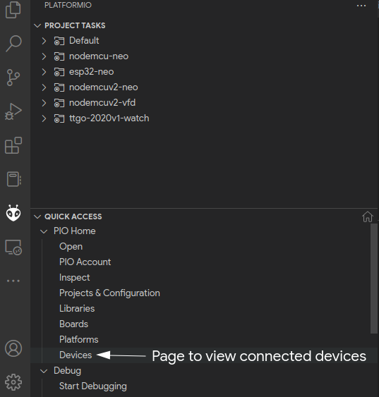
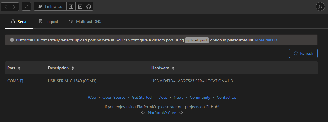
First, you want to check that PlatformIO can see the device. Plug your NodeMCU via a micro USB cable into your computer; if everything goes right, it will automatically pick it up.
If it doesn't show here, then your NodeMCU is detected/recognised by your computer. The first thing to check is to try a new USB cable and port. It needs to be able to carry data which quite a few of the cheap cables can't. You might need to install a driver, so check the bottom of your NodeMCU to see if it wants you to install a driver for a 'CH304g', 'CP2021', etc. As a last step, you can also reflash the firmware.
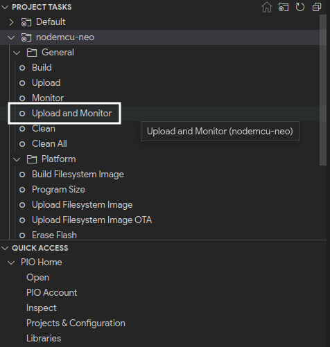
If your NodeMCU shows up, great! Let's upload and monitor the result using the PROJECT TASKS panel and expand the correct compile target according to the following table:
Development Board Name |
Compile Target |
| ESP8266 ESP-12 NodeMCU (v0.9) | nodemcu-neo |
| ESP8266 ESP-12E NodeMCU (v2) | nodemcuv2-neo |
| ESP8266 ESP-12E NodeMCU (v3) | nodemcuv2-neo |
| ESP32 Development Board | esp32-neo |
If you're unsure, you can always try them all! It won't permanently brick your board, but it will fail to upload with possibly weird errors.
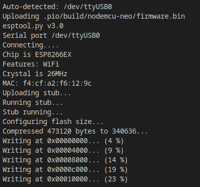
When you are ready, run the "Upload and Monitor" task; hopefully, it will start uploading!
Now you've got your brain programmed, you're onto soldering up your lights!

